ATOMIC PHYSICS
Thermionic emission
Thermionic emission definition
The
process by which free
electrons are emitted from the surface of a metal when
external heat energy is applied is called thermionic emission.
Thermionic
emission occurs in metals that are heated to a very high
temperature. In other words, thermionic emission occurs, when
large amount of external energy
in the form of heat is supplied to the free electrons in
the metals.
Metals under
high temperature
When
heat energy applied to the metal is increased to a higher
value, the free electrons gain enough energy and overcome the
attractive force of the atomic nucleus, which holds the free
electrons in the metal. The free electrons, which overcome the
attractive force of the nuclei, break the bonding with the
metal and jumps into the vacuum.

The
free electrons, which are escaped from the surface of a metal
when heat energy is supplied, are called thermionic . Thermionic
emission process plays a major role in the operation of
electronic devices.
Thermionic
emission depends on heat applied to the metal and work
function of the metal
The
number of free electrons escaped from the metal is depends on
the amount of heat applied to the metal and the work function
of the metal.
Heat applied to the metal:
If
large amount of heat is applied to the metal, large number of
free electrons gains enough energy and breaks the bonding with
the metal.
The free electron, which breaks the bonding with the metal,
jumps into the vacuum.
On
the other hand, if less amount of heat is applied to the
metal, less number of free electrons gains enough energy and
breaks the bonding with the metal. The free electron, which
breaks the bonding with the metal will jumps into the vacuum.
Hence,
the number of free electrons emitted from the metal increases
with increase in heat. Thus, the free electrons emitted from
the surface of metals are directly proportional to the
temperature of the metals.
The
minimum temperature at which the metal starts emitting the
free electrons is called threshold temperature.
If
the temperature of the metal is below the threshold
temperature, the metal does not emit the free electrons. On
the other hand, if the temperature of the metal is equal to
the threshold temperature or greater than the threshold
temperature, the metal emits the free electrons.
Production of X-rays
Summary
- A current is passed through the tungsten filament and heats it up.
- As it is heated up the increased energy enables electrons to be released from the filament through thermionic emission.
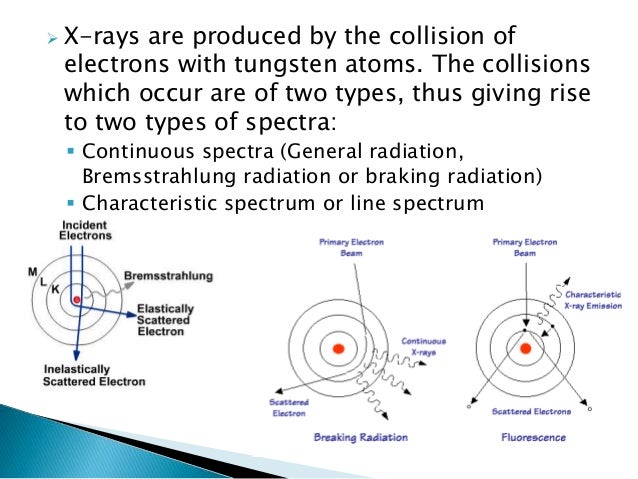
- The electrons are attracted towards the positively charged anode and hit the tungsten target with a maximum energy determined by the tube potential (voltage).
- As the electrons bombard the target they interact via Bremsstrahlung and characteristic interactions which result in the conversion of energy into heat (99%) and x-ray photons (1%).
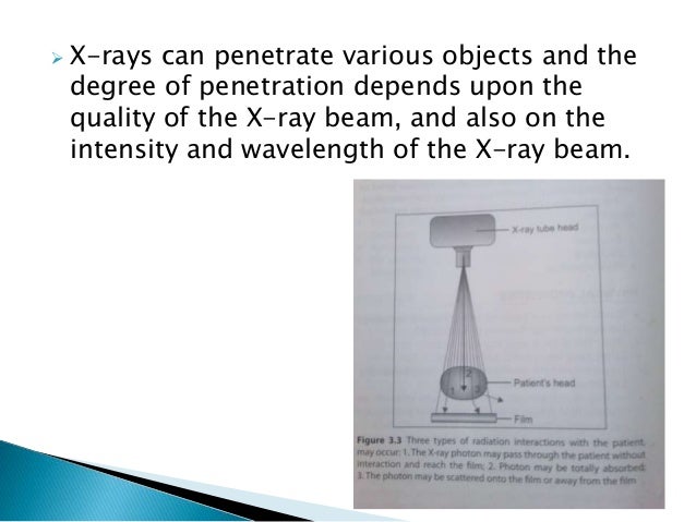
- The x-ray photons are released in a beam with a range of energies (x-ray spectrum) out of the window of the tube and form the basis for x-ray image formation.
Equipment

Cathode
Filament- Made of thin (0.2 mm) tungsten wire because tungsten:
- has a high atomic number (A 184, Z 74)
- is a good thermionic emitter (good at emitting electrons)
- can be manufactured into a thin wire
- has a very high melting temperature (3422°c)
- The size of the filament relates to the size of the focal spot. Some cathodes have two filaments for broad and fine focusing
- Made of molybdenum as:
- high melting point
- poor thermionic emitter so electrons aren't released to interfere with electron beam from filament
- Negatively charged to focus the electrons towards the anode and stop spatial spreading
Anode
- Target made of tungsten for same reasons as for filament
- Rhenium added to tungsten to prevent cracking of anode at high temperatures and usage
- Set into an anode disk of molybdenum with stem
- Positively charged to attract electrons
- Set at angle to direct x-ray photon beam down towards patient. Usual angle is 5º - 15º
- Target, focus, focal point, focal spot: where electrons hit the anode
- Actual focal spot: physical area of the focal track that is impacted
- Focal track: portion of the anode where the electrons bombard. On a rotating anode this is a circular path
- Effective focal spot: the area of the focal spot that is projected out of a tube

Stationary anode: used in mobile fluoroscopy, dental radiology and ward radiography. Consists of an anode fixed in position with the electron beam constantly streaming onto one small area.
Rotating anode: used in most radiography. Consists of a disc with a thin bevelled rim of tungsten around the circumference that rotates at 50 Hz. Because it rotates it overcomes heating by having different areas exposed to the electron stream over time. It consists of:
- Molybdenum disk with thin tungsten target around the circumference
- Molybdenum stem, which is a poor conductor of heat to prevent heat transmission to the metal bearings
- Silver lubricated bearings between the stem and rotor that have no effect on heat transfer but allow very fast rotation at low resistances
- Blackened rotor to ease heat transfer
Heating of the anode
This is the major limitation of x-ray production.
Heat (J) = kVe x mAs
or
Heat (J) = w x kVp x mAs
key:
kVe = effective kV
w = waveform of the voltage through the x-ray tube. The more uniform the waveform the lower the heat production
kVp = peak kV
mAs = current - exposure time product
kVe = effective kV
w = waveform of the voltage through the x-ray tube. The more uniform the waveform the lower the heat production
kVp = peak kV
mAs = current - exposure time product
CATHODE RAYS

MORE OVER ABOUT CRO CLICK HERE
The electrons are produced at the cathode by thermionic emission
and are accelerated towards the screen by the anode which is connected
to the terminal of the extra high tension battery.
The thermionic
emission is the process whereby metal surfaces emit electrons when
heated.
The tube is evacuated to avoid electrons interacting with any particle
before they reach the screen.
When the cathode rays hit the florescent
screen, the screen glows. This shows that electrons posses momentum and
therefore have mass.
""'Properties of cathode rays""'
i. They are negatively charged
ii. They travel in a straight line
iii. They are deflected by both magnetic and electric fields (this proves that they carry a charge)
iv. They cause fluorescence in certain materials.
v. When cathode rays are stopped by heavy metals, x-rays are emitted.
vi. They are electrons moving with high speeds.
Verification that electrons travel in a straight line
If an opaque object (Maltese cross) is placed in the path of the cathode rays, a sharp shadow of the Maltese cross is cast on the screen.
Shadow of the Maltese cross cast on the florescent screen
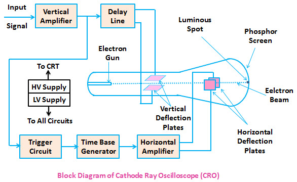
Applications
Cathode Ray Tube, TV and Computer Monitors, and the Oscilloscope
A cathode ray tube consists of a vacuum tube that contains one or more electron guns used to excite phosphors on a screen to produce images.
What is a cathode ray oscilloscope (CRO) ?
CRO is a type of electronic test instrument that allows observation of constantly varying signal voltages, usually as a two-dimensional plot of one or more signals as a function of time.
You'll be like - “Just Tell me the uses ?!!”
Alright, there you go !
- Measure short time interval: A CRO can be used to measure time interval between the pulses in a signal which are displayed on the screen. By counting the units of separation of the pulses and multiplying it with the set time/div reading of the knob, one can precisely state the time interval[1] .
- Measure potential difference (as a voltmeter): A CRO provides infinite (practically very high) input impedance just a usual voltmeter while measuring the potential difference. The only difference between them is that the CRO utilizes its screen to display the nature of the voltage being measured, which enables the user to observe the characteristics of the signal.
- Current measurement: Voltage measurements can be used to calculate current flow through a device or through any portion of a circuit. From Ohm’s Law[2] :
E = I x R
Where E = electromotive force in volts
I = current in amps
R = resistance in ohms
Solving for I:
I = E/R
- Examination of Waveform: Once, the corresponding signal has been measured and displayed, it can be analyzed to obtain its various parameters such as peak-peak voltage, this period etc.
- Measurement of phase: When sine-wave signals of different frequencies are input to the horizontal and vertical amplifiers a stationary pattern is formed on the CRT when the ratio of the two frequencies is an intergral fraction such as 1/2, 2/3, 4/3, 1/5, etc. These stationary patterns are known as Lissajous figures and can be used for comparison measurement of frequencies[3] .
- Measurement of frequency: Frequency can be calculated by simply taking the inverse of the time period of the signal obtained.
Image credits: Google
Footnotes
Tipalti makes mass payouts to global suppliers, partners, affiliates, publishers, and freelancers.
What Is Radioactivity?
What causes radioactivity?
As its name implies, radioactivity is the act of emitting radiation spontaneously. This is done by an atomic nucleus that, for some reason, is unstable; it "wants" to give up some energy in order to shift to a more stable configuration.
you can get more here download radioactivity [pdf]
Difference Between Thomson and Rutherford Model of Atom
Main Difference – Thomson vs Rutherford Model of Atom
Thomson model of atom is one of the earliest models to describe the structure of atoms. This model is also known as the plum pudding model
due to its resemblance to a plum pudding. This explains that this atom
is a spherical structure made out of a positively charged solid material
and the electrons are
embedded in that solid. But this model was rejected after the discovery
of atomic nucleus. Rutherford model of atom describes the atomic
nucleus and the location of electrons in an atom. It was proposed who
described that an atom is composed of a central solid core which is
positively charged and electrons are located surrounding this solid
core. However, this model was also rejected because it could not explain
why the electrons are not attracted to the nucleus. The main difference
between Thomson and Rutherford model of atom is that Thomson model does not give details about the atomic nucleus whereas Rutherford model explains about the nucleus.
Key Areas Covered
1. What is Thomson Model of Atom
– Definition, Model, Drawbacks
2. What is Rutherford Model of Atom
– Definition, Model, Drawbacks
3. What is the Difference Between Thomson and Rutherford Model of Atom
– Comparison of Key Differences
Key Terms: Alpha Particles, Atom, Electron, Gold Foil Experiment,
Nucleus, Plum Pudding Model, Rutherford Model of Atom, Thomson Model of
Atom– Definition, Model, Drawbacks
2. What is Rutherford Model of Atom
– Definition, Model, Drawbacks
3. What is the Difference Between Thomson and Rutherford Model of Atom
– Comparison of Key Differences

What is Thomson Model of Atom
Thomson model of atom is the structure
of an atom proposed by the scientist, J.J.Thomson, who was the first
person to discover the electron. Soon after the discovery of the
electron, the atomic model was proposed saying that the structure of an
atom is like a “plum pudding”.
Thomson model of atom is described base on three main facts:- Atoms are composed of electrons.
- Electrons are negatively charged particles.
- Atoms are neutrally charged.

Figure 1: Thomson Model of Atom
Thomson proposed that since electrons
are negatively charged and atoms are neutrally charged, there should be a
positive charge in the atom in order to neutralize the negative charge
of electrons. He proposed that the atom is a solid, positively charged,
spherical structure and electrons are embedded in that sphere. Since
this structure looks like a pudding with plums scattered on it, it was
called the plum pudding structure of atom. However, this structure was
rejected after the discovery of atomic nucleus.
Drawbacks of Thomson Model of Atom
- No details about atomic nucleus.
- No details about atomic orbitals.
- No explanation about the protons or neutrons.
- States that the atom has a uniform distribution of mass, which is wrong.
Rutherford model of atom describes that
the atom is composed of an atomic nucleus and electrons surrounding the
nucleus. This model caused to reject the Thomson model of atom.
Rutherford model was proposed by Ernst Rutherford after the discovery of
the atomic nucleus.
The gold foil experiment was used by
Rutherford to propose this atomic model. In this experiment, alpha
particles were bombarded through a gold foil; they were expected to go
straight through the gold foil. But instead of straight penetration,
alpha particles turned into different directions. This experiment
indicated that there is a positively charged, solid material in the
middle of the atom while the rest of the atom has more empty space. This
solid core was named as the nucleus.

Figure 2: Rutherford Atomic Model
- The atom is composed of a positively charged center which is called the nucleus. This center contained the mass of the atom.
- Electrons are located outside the nucleus in orbitals at a considerable distance.
- The number of electrons is equal to the number of positive charges (later called protons) in the nucleus.
- The volume of the nucleus is negligible when compared to the volume of the atom. Hence, most of the space in the atom is empty.
Drawbacks of Rutherford Model of Atom
Later, Rutherford model was also
rejected because it could not explain why the positively charged nucleus
and electrons are not attracted to each other.
Difference Between Thomson and Rutherford Model of Atom
Definition
Thomson Model of Atom: Thomson model of atom states that electrons are embedded in a positively charged solid material which is spherical in shape.Rutherford Model of Atom: Rutherford model of atom describes that an atom is composed of an atomic nucleus and electrons surrounding the nucleus.
Nucleus
Thomson Model of Atom: Thomson model of atom does not give any details about the atomic nucleus.Rutherford Model of Atom: Rutherford model of atom explains about the atomic nucleus.
Electrons
Thomson Model of Atom: Thomson model of atom states that electrons are embedded in a solid material.Rutherford Model of Atom: Rutherford model of atom states that electrons are located around a central solid material.
Shape of Atom
Thomson Model of Atom: Thomson model of atom indicates that the atom is a spherical structure.Rutherford Model of Atom: Rutherford model of atom indicates that an atom has a central solid core surrounded by electrons.
Conclusion
Thomson model of atom and Rutherford
model of atom are two models proposed by J.J.Thomson and Ernest
Rutherford, respectively in order to explain the structure of an atom.
The main difference between Thomson and Rutherford model of atom is that
Thomson model does not give details about the atomic nucleus whereas
Rutherford model explains about the nucleus.
Difference Between Alpha Beta and Gamma Radiation – Summary
| Property | Alpha radiation | Beta radiation | Gamma radiation |
| Nature of particle | A helium nucleus | An electron/positron | A photon |
| Charge |  |
 |
0 |
| Mass |  |
 |
0 |
| Speed | ~0.05c | up to 0.99c | c |
| Ion pairs per cm of air | ~1 000 000 | ~10 000 | ~10 |
| Interaction with perpendicular magnetic fields | Some deflection | Large defleciton | No deflection |
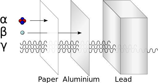
| Stopped by | Thick sheet of paper | Few mm of aluminium sheet | (to some extent) A couple of cm of a block of lead or few metres thick concrete |
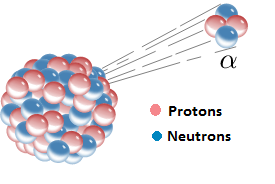
Alpha Beta and Gamma Particles
- Alpha radiation consists of alpha particles or helium nuclei (
), that is, a particle of alpha radiation consists of two protons and two neutrons bound together.
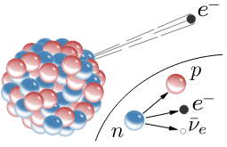
- Beta radiation could refer to either beta minus radiation, where electrons (
) are emitted or beta plus radiation, where positrons (
) are emitted.
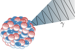
- Gamma radiation refers to the radiation of an electromagnetic wave in the gamma range. It can also be considered to be a photon (
).
Charge of Alpha Beta and Gamma Radiation
- Alpha particles have a charge of (
) from its two protons, where
.
- For beta radiation, an electron has a charge of
. A positron, being the antiparticle of the electron, has a charge of
.
- Photons which carry gamma radiation are not charged.
Mass of Alpha Beta and Gamma Radiation
- Alpha particles are made of four nucleons. Therefore, they have a mass of approximately
, where
. So, the mass of an alpha particle is 6.64×10⁻²⁷ kg = 3.73 GeV/c2.
- Electrons and Positrons, which make up beta particles, are antiparticles of each other. This means that they both have the same mass. The mass of an electron/positron is 5.49×10⁻⁴ u = 6.64×10⁻²⁷ kg = 511 keV/c2.
- Photons are massless, so gamma radiation carry no mass.
Speed of Alpha Beta and Gamma Radiation
- Alpha decay only takes place when masses of the daughter nucleus (
) and the alpha particle together (
) is less than the mass of the parent nucleus (
). The difference in masses (
) is given as kinetic energy to both the alpha particle and the daughter nucleus.To conserve momentum, the daughter nucleus and the alpha particle must travel in opposite directions. In addition, the alpha particle, being much lighter than the typical daughter nucleus, carries off most kinetic energy (again, to conserve momentum). Typically, the alpha particles have speeds of about 5% the speed of light (
, where
speed of light = 3×10⁸ m s-1. For a given alpha decay the kinetic energy, and therefore the speed of the alpha particle, takes a specific value which can be calculated from the mass differences in nuclei and from the law of conservation of momentum.
- For beta decay, there are three products that share the
kinetic energy available. In this case, the kinetic energy may be shared
between particles in any way. As a result, the beta particles can take
a range of values. Typically, they take on values of up to
.
- Gamma radiation consists of photons. They travel at the speed of light,
. They do carry specific energies, however, corresponding to the specific transition of nuclear energy levels that caused them to be emitted.
Ionising Power of Alpha Beta and Gamma Radiation
- Alpha particles can produce about 1 000 000 pairs of ions per centimetre as they travel through the air. This is relatively high. This is because they have a relatively large mass and they move slowly, allowing them to interact more with air molecules.
- Beta particles produce about 10 000 pairs of ions per centimetre in air.
- Gamma rays (photons) can produce about 10 pairs of ions per centimetre in air.
Effect of Magnetic Field on Alpha Beta and Gamma Radiation
- Alpha particles have a charge, so if a magnetic field is applied perpendicular to its path, the alpha particle shows some deflection.
- Beta particles also have a charge. Compared to alpha particles, beta particles’ charge is half that of an alpha particles’ charge. On the other hand, speeds of beta particles are much larger than those of alpha. As a result, beta particles are deflected more strongly by magnetic fields applied perpendicular to their paths. When placed under the same magnetic field, a beta minus particle bends in the opposite direction to that of an alpha particle, while a beta plus particle would bend in the same direction as does the alpha particle.
- Photons are not charged and so they do not get deflected by magnetic fields.
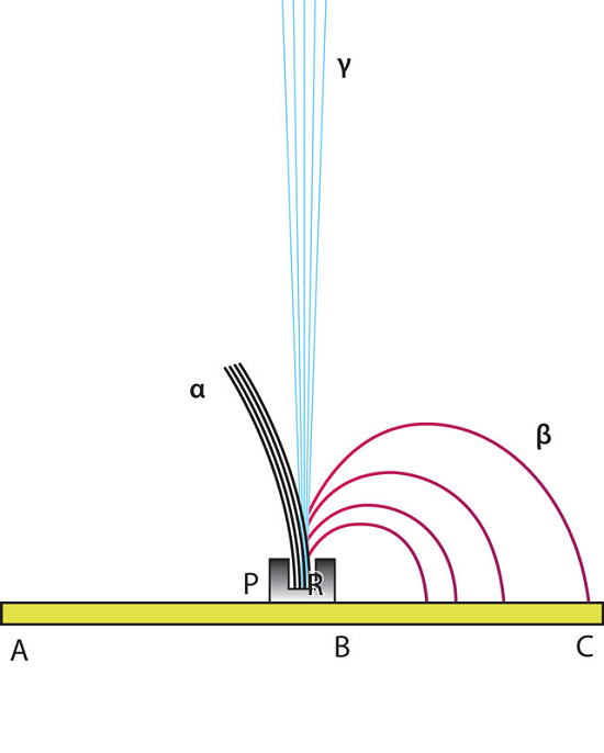
From Marie Curie’s Demonstration of the Behavior of 3 Types of Radiation
Ability to Stop Alpha Beta and Gamma Radiation
- Alpha particles are strongly ionising. So as they travel through matter, they lose their energy much more quickly. Hence, they can be stopped easily. Alpha particles can travel a few centimetres in the air before they are stopped. They can also be stopped by a thick piece of paper. They cannot penetrate through human skin, either, so they are not as dangerous, so long as they remain outside our bodies. Once they are inside the body, they can cause much more damage than beta and gamma since they have a much stronger ability to ionise. (In a famous case, Alexander Litvinenko, a former Russian secret agent, is believed to have been deliberately poisoned with polonium-210, an alpha emitter. It is also difficult to detect alpha particles since they cannot leave the body once they are inside. However, traces of alpha radiation had been found where he had used public restrooms).
- Beta particles can travel several metres in the air, but they can be stopped by a sheet of aluminium several millimetres thick.
- Gamma photons interact the least with matter, and consequently they are much harder to stop. Several centimetres of lead or a few metres of concrete is needed to appreciably reduce the intensity of gamma radiation.


Comments
Post a Comment